Note: This page best viewed with at least 800x600 resolution
Boxing factory control arms: Title match by Chris Neighbors Feb. 22, 2000
While reinforcing my torque boxes, I decided (on a whim) to box my factory arms while they were out. Most wouldnt bother with the trouble, especially with the lowers, but I wanted to see just what it would take I plan on buying a set of aftermarket lowers later, but will run the boxed uppers. It does little good to box the control arms and run the stock bushings, as they are very compliant (especially the lower front). Plan on replacing the bushings as well, to enjoy the maximum benefit. Be forewarned: Urethane bushings are hard on torque boxes, and are the main cause of t-box failure on a street driven car. They tend to bind in corners, and may cause erratic and poor handling, increased road noise, and a harsh ride. Proceed at your own risk
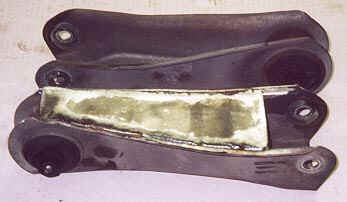
I started out by installing an upper arm on the rear end (which was out of the car ), and letting it go until it bottomed out on the axle. I eyeballed a line of sight that cleared the bushing ear, and marked the arm.
This would be the extent of the plate. I remembered William Mathis had a blurb and drawings for control arm boxing, so I got out my copy of Mustang Performance Handbook, Volume II. I laid out the upper plate, as detailed by Mathis, on posterboard and cut out. When I laid it on the arm, however, I wasnt satisfied with the edge location, and subsequent weld seam. I narrowed the template until I felt comfortable. I laid out the LCA boxing, and tweaked accordingly. Once happy with the fit of both, its time to "cut metal"
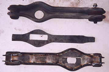
I purchased a plasma cutter mid-last year, and it works great for odd shaped parts like the LCA plate. Its a luxury, but the job can be accomplished without it by using a torch or jigsaw. In my case, I transferred the LCA template profile to a scrap piece of ¼" luan plywood. The torch tip of my plasma is 5/16" diameter,
so I offset the template profile 5/32" (to make the burned part the right size). I cut the wooden template out with a coping saw, and sanded the edges. The good thing about the plasma is it burns fairly cool in a localized area (very narrow kerf), and therefore rarely even scorches the wooden templates. I clamped the template to a piece of 1/8" strip, and cut the plates out, letting the torch tip follow the pattern. It takes about three minutes per plate to cut out, but with a template available, exact copies can be produced in the same short timeframe. I traced the upper plates onto the strip, and used a yardstick as my straightedge to cut them out.
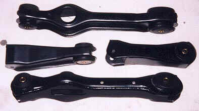
The plates need to be bent slightly in several spots to match the profile of the arms. Mark lines where appropriate, secure in a vise, and bend as required (it took about three bends per end to get mine to match). Once the bends are satisfactory, sand/grind the edges of the plates, and the arms where the weld seam will be located. Clamp the plates onto the appropriate arm with a couple of four-inch C-clamps, and weld away! Its a good idea to skip weld the plates on, to avoid warping/distorting the arms. I welded in 1-1/2" increments, skipping from side to side and front to back. Continue until the plate is fully welded; repeat on the others Grind the welds as required.
Bushing removal:
Upper front: Place a short section of 2" pipe vertically on the shop press. Center the control arm over the pipe, with the flange of the bushing shell against the pipe. Using a suitably sized ram, press the bushing out. The bushing should come out fairly easily, but you may have to drive the ram back out if rubber gets forced between it and the shell.
Upper rear: There are several methods for getting the uppers out. Some use a hole saw, drilling halfway through both sides, others use a small drill bit and drill multiple holes around the interface of the bushing and shell to get it out. I thought I would try something a bit different, and cooked up a puller, similar to that illustrated in the factory service manual. I went to the local hardware store and bought a 2" pipe nipple/coupling (make sure it's at least 2" long; I bought a 4" piece. It's I.D. is about 2", which matches the shell flange very well.), a length of 7/16" all-thread, a handful of nuts ( extras for spares), flat washers large to not pass through the pipe, and enough flat washers to get me down to the 7/16" all-thread (3/8" flats fit 7/16" fasteners VERY well...). I had all the parts for the "receiver", but needed a "pusher". Looking through my toolbox, I found my 1-1/4", 1/2" drive socket had the perfect O.D. to fit inside the steel shell. I ran a couple of nuts up the all-thread (although cutting a "length" would be better), followed by a stack of washers and the pipe coupling. I placed the all-thread through the bushing from the backside, and placed the socket, a couple of flat washers, and a nut on the exposed thread. I tightened the nuts to draw the socket into the shell, pushing the bushing out. I had to tap the socket out afterwards, as a small amount of rubber gets sheared between the socket and shell. On the driver's side, I had to unbolt the bracket that retains the brakeline, to give me enough room for the socket. I plan to cut the pipe, weld the washers to it, and cut the all-thread to length, in an attempt to "make it look pretty". All in all, I had about $7 in hardware, and it takes about three minutes per side, including set-up.
Lower bushings: The lower control arm bushings are vulcanized (or somehow "adhered") to the bushing shell, nearly prohibiting removal by a shop press. I managed to get the rears pressed out with the same set-up as the upper fronts, but the oval fronts were not budging. Many prefer and recommend drilling these out. I had very little luck with the drill, and impatience got the better of me. I fired up the torch and proceeded to burn the things out. Once they were ablaze, I let them burn while I painted the arms (keeping an eye on them, while they burned in the middle of my driveway, over an old pizza tray). The smoke was terrible, but they came out with little fuss after being scorched, LOL! I used a carbide cutter in a die grinder to remove the vulcanized residue. Messy, noxious, but quite effective.
Bushing installation:
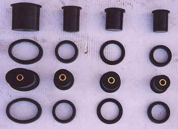
The Energy Suspension kit comes with an instruction sheet, and a small bag of lube. Once you sort out the proper bushing location, lube the inside of the shell, the outside of the corresponding bushing, and press into place. Mine went in more than halfway by hand, and were seated quite easily with a few taps with a dead-blow hammer. Install the appropriate washers, and install the arms. Torque to spec, with the weight of the car on the system (i.e. jackstands under the axle housing).
Energy Suspension rear control arm bushing kit: 4.3115G ($72.95 from Summit)
Part number |
Location |
O.D. |
Length |
Bushing |
3076 |
lower front |
2.047 x 3.030 |
2.665 |
3109 |
3027 |
lower rear (axle) |
1.855 |
2.555 |
3101 |
3028 |
upper front |
1.973 |
2.080 |
3099 |
3029 |
upper rear (axle) |
1.691 |
2.162 |
3098 |